Motor switches for model railway
• Motorized switches, quiet and slow motion• Small size
• Included motor with planetary transmission
• Direct replace of electromagnetic motor or motoric switches
• Possibility to adjust the stroke degrees
• Integrated switching contacts
• Easy instalation
• Easy to set the basic position of the needle
The switches are used for the electrical control of two-position mechanisms in models, typically switches or mechanical signals and railcrossings.
The stroke is adjusted in several steps by the position of the pin in the carrier. The sliding mechanism ensures a smooth approach to the end position and its arrest.
The power supply is direct current and alternating current in the range of 9–16 V, consumption approx. 150 mA during operation. The mechanism is equipped with limit switches position, the control power supply can be connected permanently, after reaching the appropriate position, the current consumption and movement are automatically disconnected.
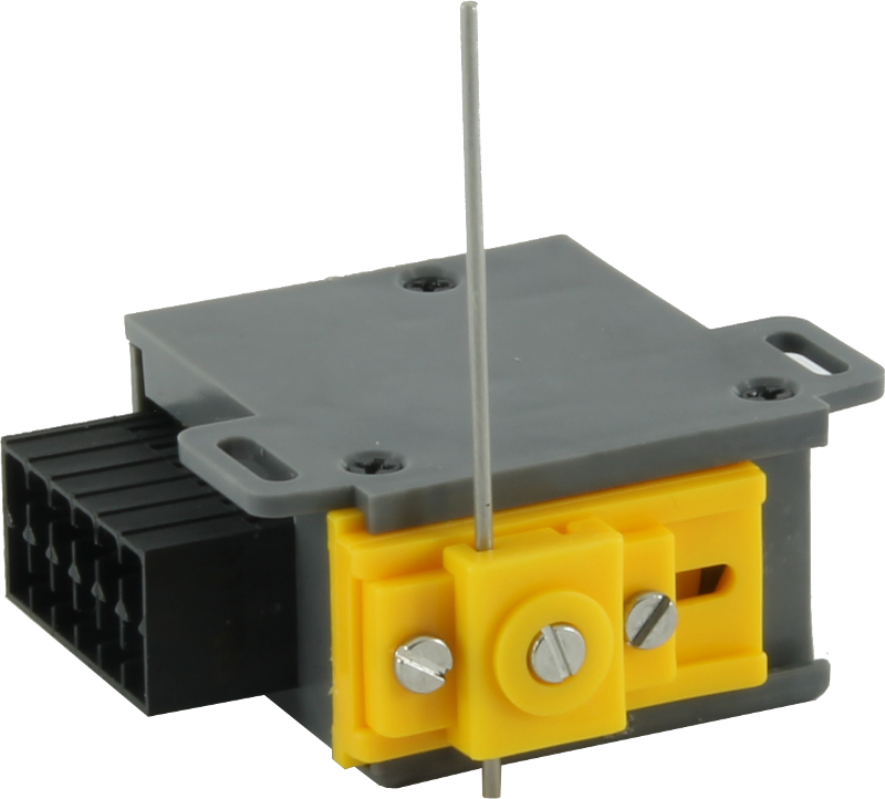
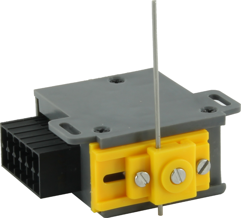
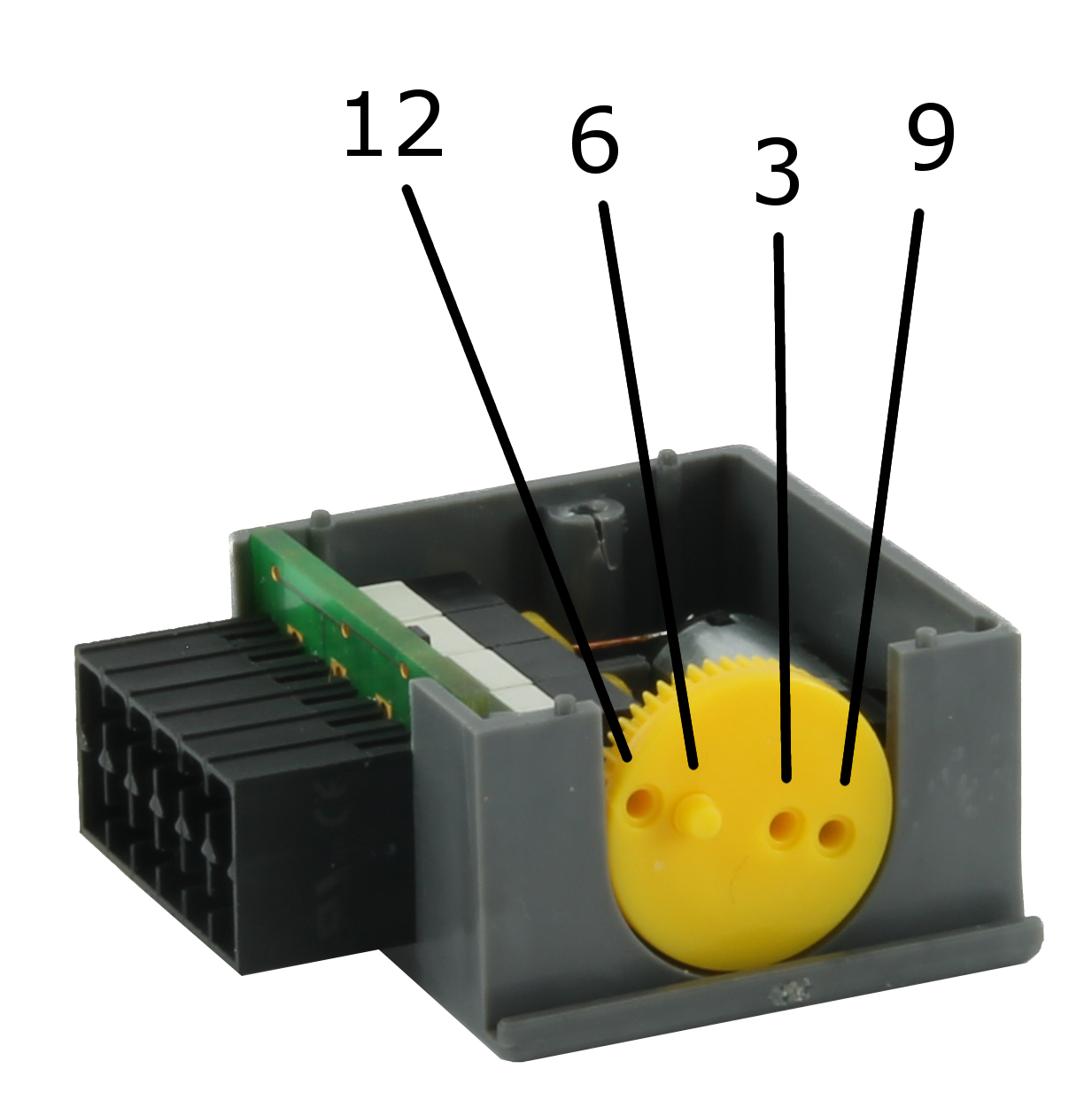
MP1
Basic model railway switch
• Miniature scantlings 28x40mm (w x l)
• Inbuilt motor with planetary transmission
• Direct replace of electromagnetic motor switch with three-core connection
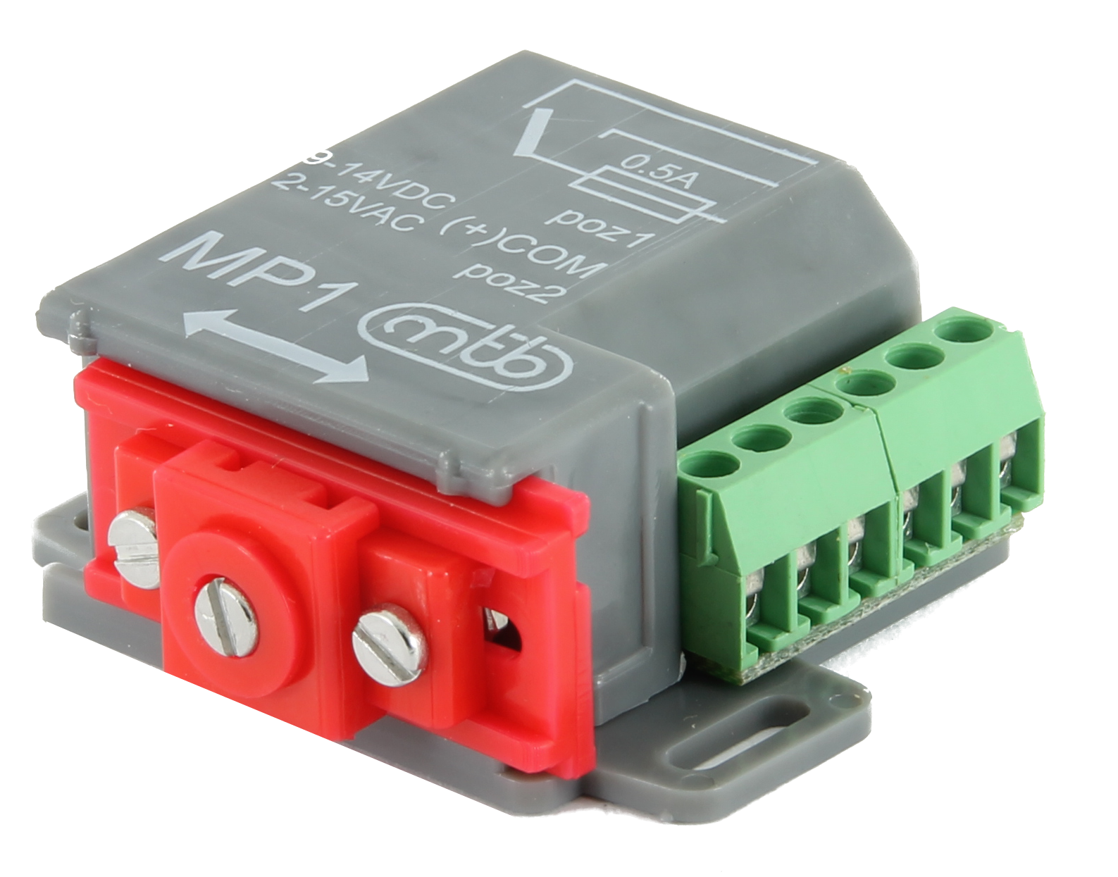
The motor switch is used for electric actuation of the two–position mechanisms in models, such as turnout points or mechanical signals and barriers.
The stroke can be set in three steps 3 mm, 6 mm, 9 mm – see the illustration. The cam mechanism provide slow end position stop and lock.
Electrical connection is the same as old–style electromagnetic switch and MP1 can directly replace them without changes in wiring of model layout scheme.
MP1 is equipped with one SPDT contact for auxiliary purposes, like frog polarisation, with capacity 1A.
 Manual download here
Electric switch on of motor switch
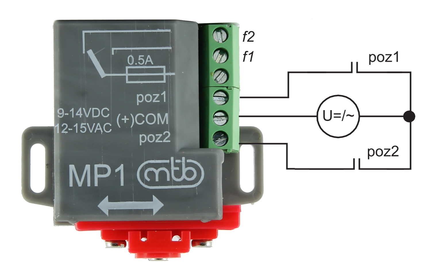
Connect to the COM+ terminal with DC powersupply. The F1 contact will close once the movement ends up at the Position 1 (or the Position 2 in case of the F2 contact respectively)
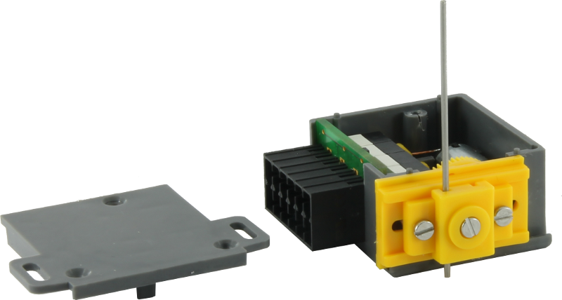
MP4
Advanced model railway switch
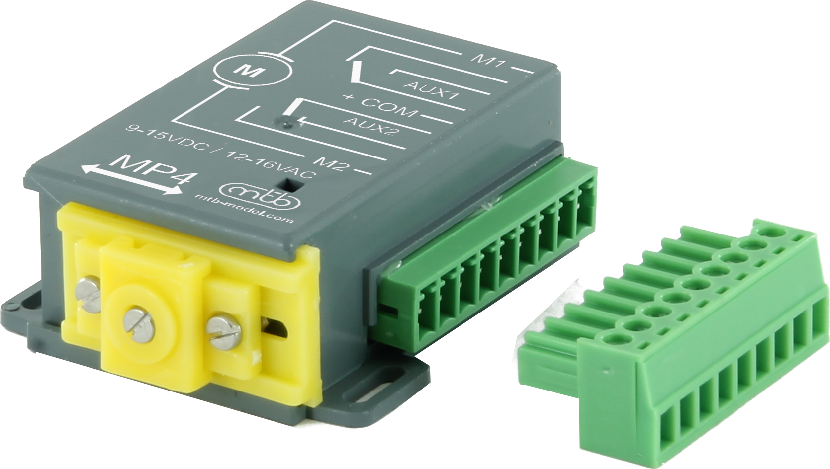
• Miniature size
• Universal connection of electromagnetic or motoric switch
• Setting of 4 stroke ranges 3, 6, 9 a 12 mm
• Two auxiliary switching contacts
• Detachable connector for easier installation
Both DC and AC power supplies are available, with consumption aprox 150 mA during motion. The mechanism has a position end limit switch, i. e. the control voltage can be applied permanently, to be disconnected automatically once a respective position is reached and the motion stops.
Electrical connection is the same as old–style electromagnetic switch.
The stroke can be set in three steps 3 mm, 6 mm, 9 mm and 12mm – see the illustration. The cam mechanism provide slow end position stop and lock.
MP5 is equipped with two SPDT contacts (1A) for auxiliary purposes. Easy installation with removable screwless connector.
Manual download here
Electric switch on of motor switch
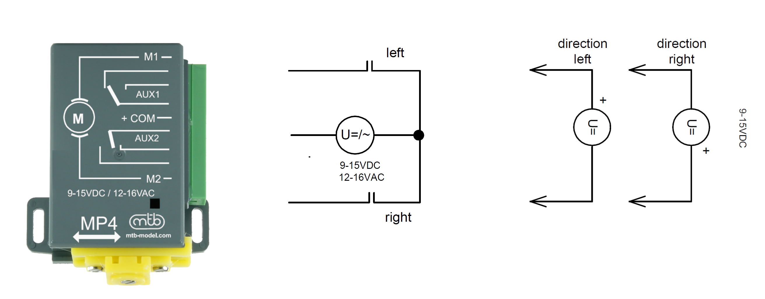
Integration with 3 conductors like electromagnetic switch Integration with 2 conductors like motor switch
MP8
Impulse motor switch

• Universal connection as electromagnetic switch
• Impulse control
• 4 stroke stages 3, 6, 9 and 12 mm
• 1x independent switching contact + 2x reverse signaling outputs
• Convenient installation with removable connector
The stroke is adjustable in four stages of 3, 6, 9 and 12 mm by positioning the pin in the sleeve. The coupling mechanism ensures a smooth travel to the end position and its locking.
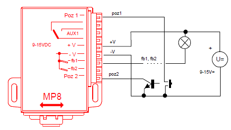
The MP8 switch serves as a replacement for the standard two-coil switch, with short-pulse control. Supply voltage 9-14V DC, which must be permanently applied (+V and -V) . The transfer to the end position is provided by a memory relay which is operated by a short pulse (min 40ms) from the control device/switch. The pulse inputs are two POS1,POS2, switching the input to pole -V (common zero) will start the movement. The electronics of the shifter ensure a smooth changeover and travel to the end position, even if the control pulse has already passed. The outputs (fb1, fb2) are designed to signal the end position of the inverter by means of an LED or a bulb, these contacts switch after reaching the negative pole of the voltage (-V). Or they can be used for electronics as a feedback of the device position.
For additional use, the MP8 switch is equipped with one isolated switching contact with a capacity of 1A. Limit switches and relays ensure position travel even after the interrupted power supply is restored.
Electric switch on of motor switch
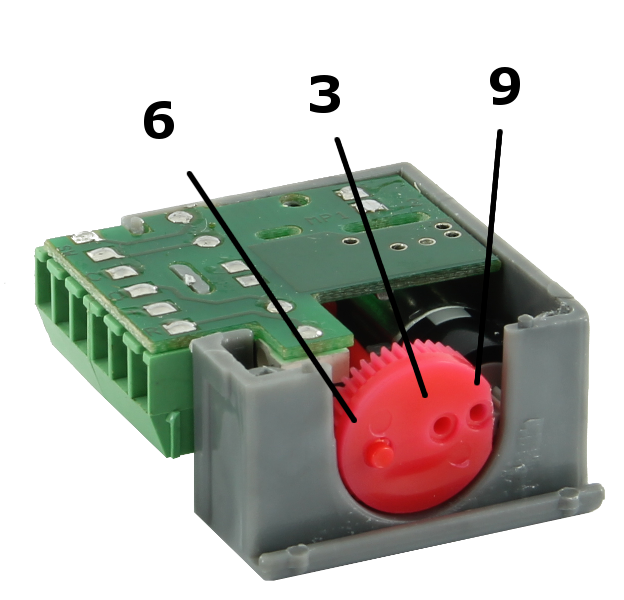
MP10
Advanced model railway switch
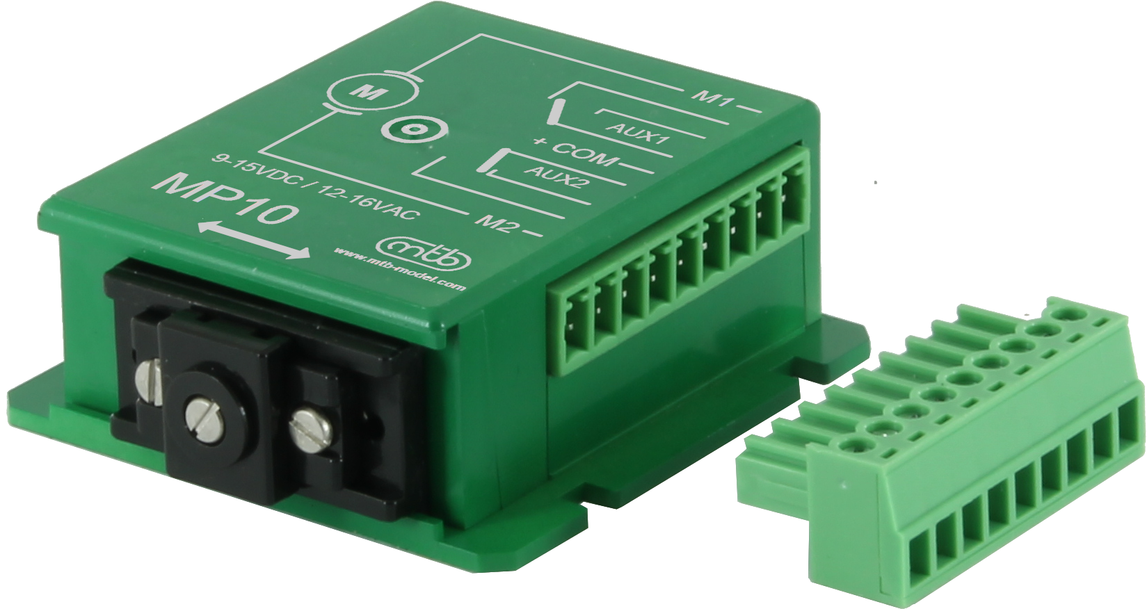
• Slow movement, higher feed force
• Two- and three-wire control
• Setting of 4 stroke ranges - 3.5, 6, 9.5 a 12.5 mm
• Two auxiliary switching contacts
• Detachable connector for easier installation.
The MP10 combines the features of the basic MP1 toghether with MP5 while maintaining a low price. It is designed as a compatible replacement for the Tortoise (USA) motor switch, with same mounting dimensions.
Modifed mechanical transmission increases power and slows down the speed of movement, the MP10 is suitable for larger ganges, like 0.
Stroke adjustable in the range of 3.5 – 6- 9.5-12.5mm.
Two independent switching contacts with a capacity of 1A.
Two-wire connection mode – position movement controled by the polarity of the power supply (like Tortoise), after reaching the end position, the motor turns off. Alternative three-wire connection mode - function same as MP1 or electromagnetic switches.
Manual download here
Electric switch on of motor switch
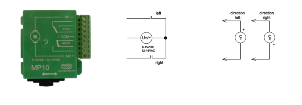
Integration with 3 conductors like electromagnetic switch Integration with 2 conductors like motor switch
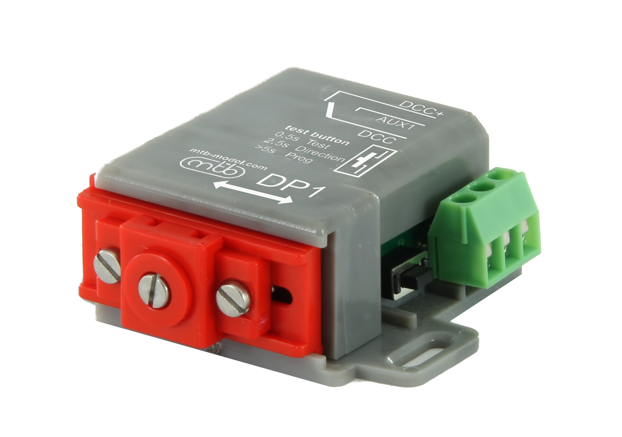
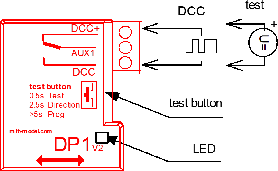
DP1
DCC
Basic model railway switch with DCC
• Dimensions and mechanical function identical with MP1
• 4 stroke levels 3, 6, 9 mm
• 1x independent switching contact
• Quick setup by push button
Přestavníky DP1 jsou vybaveny rozhraním DCC které zajišťuje příjem digitálních povelů a současně napájení chodu přestavníku. Pro napájení výhybek je vyveden 1x pomocný kontakt, který napájí signálem DCC srdcovku. Indikační LED dioda slouží pro signalizaci stavů, pro konfiguraci a testování se používá pomocné tlačítko.
DPx jsou navrženy pro snadnou instalaci a ovládání výhybek přes DCC, bez nutnosti nákupu, montáže a konfigurace samostatných DCC dekodéru příslušenství.
Manual download here
Manual download here - FR version
Electric switch on of motor switch
DP4
DCC
Advanced model railway switch with DCC
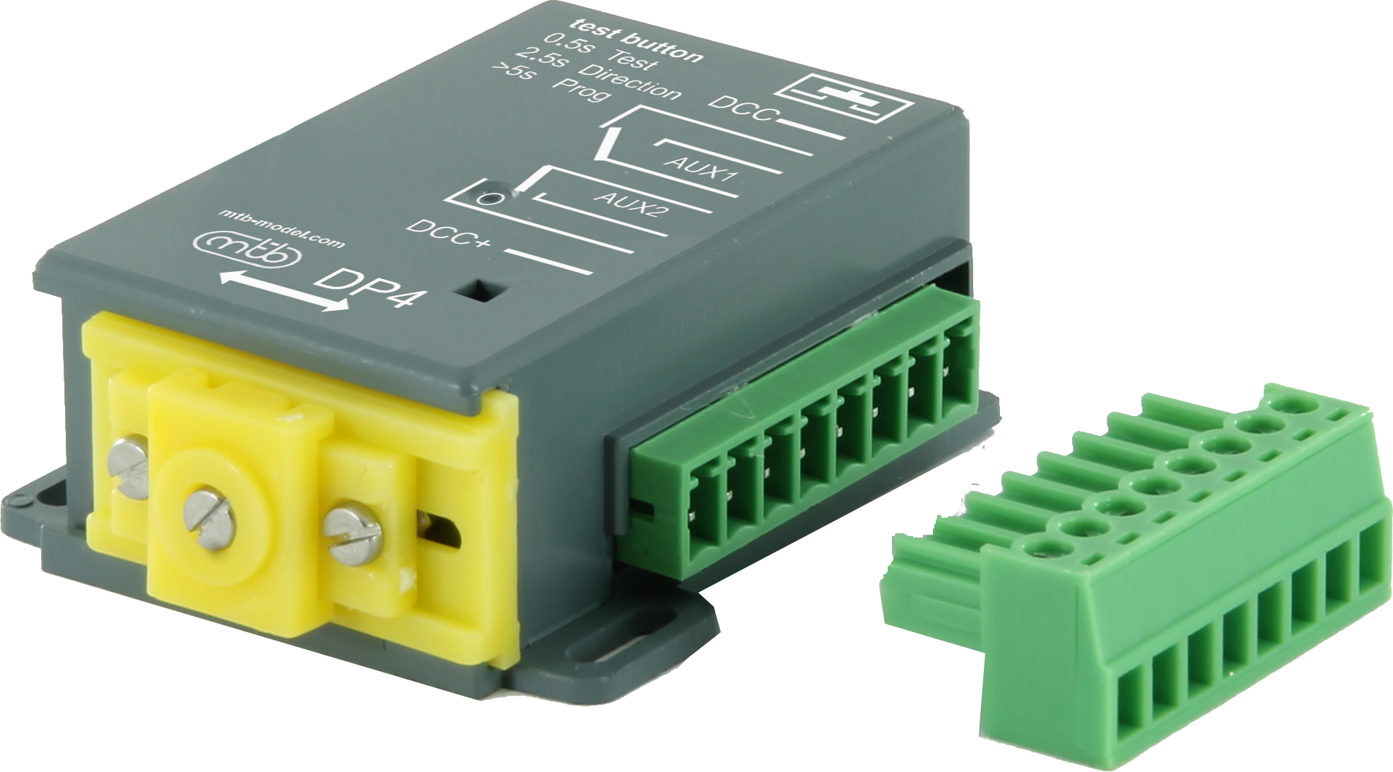
• Dimensions and mechanical function identical to MP4
• 4 setup of stroke- 3, 6, 9 and 12 mm
• Integrated double auxiliary contacts
• Quick and simple setup with the configuration button
The DP4/10 motor switches are equipped with a DCC interface that ensures the reception of the DCC commands toghether with power supply. They are also equipped with auxiliary switches AUX1, AUX2 for indicating and switching of frog polarization. The indicator LED is used for status signaling, the auxiliary button is used for configuration and testing.
DPx switches are designed for easy installation and control of switches via DCC, without the need to purchase and assembly and configuration of standalone DCC accessories decoders.
Manual download here
Manual download here - FR version
Electric switch on of motor switch
DP10
DCC
Advanced model railway switch with DCC

• Dimensions and mechanical function identical to MP10
• 4 setup of stroke - 3.5, 6, 9.5 a 12.5 mm
• Integrated double auxiliary contacts
• Quick and simple setup with the configuration button
The DP4/10 motor switches are equipped with a DCC interface that ensures the reception of the DCC commands toghether with power supply. They are also equipped with auxiliary switches AUX1, AUX2 for indicating and switching of frog polarization. The indicator LED is used for status signaling, the auxiliary button is used for configuration and testing.
DPx switches are designed for easy installation and control of switches via DCC, without the need to purchase and assembly and configuration of standalone DCC accessories decoders.
Manual download here
Manual download here - FR version
Electric switch on of motor switch
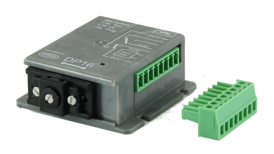
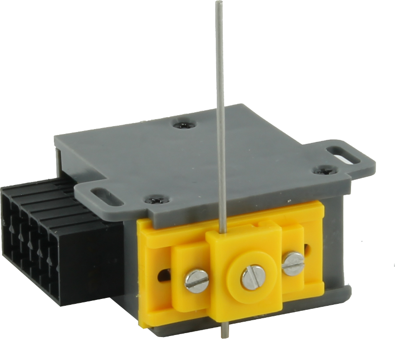
DP16
DCC
Advanced model railway switch with DCC
• additional galvanic isolated 2 manual inputs (12V, 4mA)
• Dimensions and mechanical function identical with MP10
• 4 stroke levels 3.5, 6, 9.5 and 12.5 mm
• 1x independent switching contact + 1x output for powering the frog (AUX2 terminal)
• Quick setup by push button
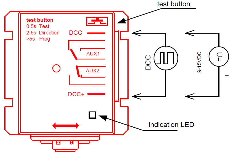
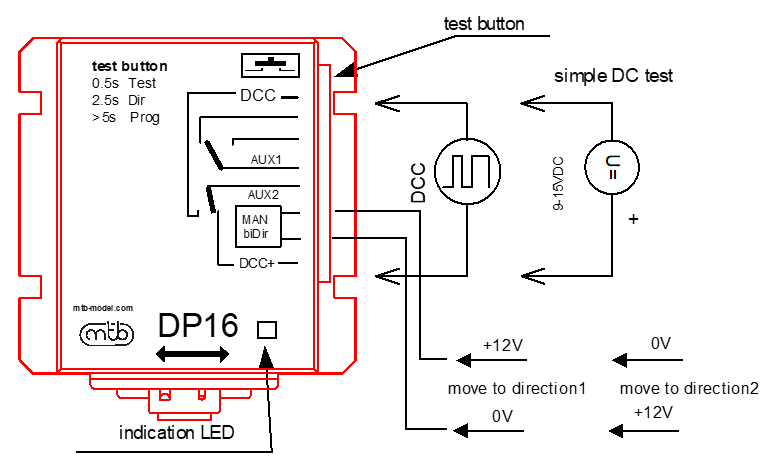
The DP16 is equipped with a DCC interface that provides reception of digital commands and also power for the operation of the switch. DP also includes Auxiliary switchi contact AUX1 for indicating and independent supply of the frog. For simplified frog supply AUX2 signal can also be used, which is connected to the DCC impuls wires.
For manual operation control two biDIR inputs are designed, which can control switch operation by applying input signal +- (12V/4mA). Polaritiy of signal determne direction or switch movement. Commands from DCC channel has higher priority over manual inputs.
Indication LED is used to signalize the status. For testing and configuration (teaching of DCC address) is used auxiliary push button.
DP16 are designed for easy installation and control of turnouts via DCC, without the need of separate accessory DCC decoder.
Electric switch on of motor switch
How to change the distance of travel
1
Unscrew 3 screws on the housing bottom.

2
Remove the slider assembly.
3
Set the pin to a desired position
4
Reassemble the set and fit the housing. Carefully retighten screws.
The switches must get in contact with cams, but beware
of plastic parts while retightening. Excessive effort might cause damage to them; try with the screw first.
Setting the length of needle
1
Unscrew screw on the check gate of motor switch

2
Set the required length of needle and screw up screw

Setting the needle longitudinal position
1
Unscrew 2 external screws on the check gate of motor switch
2
Set the required position of check gate with respect to the end position of switch